For anyone towing a trailer, understanding how the braking system works is essential. The electric trailer brakes diagram is a valuable tool that helps you visualize the components and connections involved in your trailer’s braking system. In this guide, we’ll walk through the key elements of electric trailer brakes, explain how they work together, and how to interpret a typical diagram.
What Is an Electric Trailer Brakes Diagram?
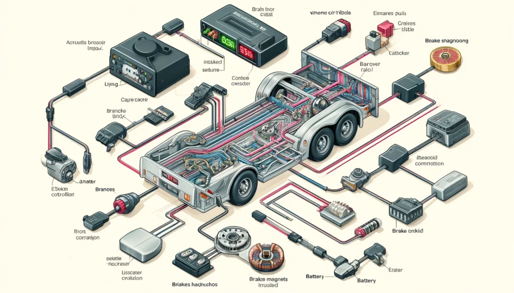
An electric trailer brakes diagram is a visual representation of the components and wiring that make up the braking system. It shows the connections between the brake controller, battery, brake magnets, and other critical parts. This diagram is essential for troubleshooting issues, performing installations, and understanding the overall function of the brakes.
Key Components in an Electric Trailer Brakes Diagram
- Brake Controller:
- The brake controller is located in the towing vehicle. It sends an electrical signal to the trailer’s brakes when the vehicle’s brakes are applied. The controller is connected to the vehicle’s brake light switch, allowing it to detect when braking occurs.
- Battery:
- The trailer’s braking system is powered by the vehicle’s battery. The battery supplies the necessary voltage to activate the brake magnets and engage the brakes.
- Wiring Harness:
- The wiring harness connects the brake controller to the trailer’s brakes. This harness typically includes wires for power, ground, and the brake signal.
- Brake Magnets:
- The brake magnets are located inside the brake assemblies on the trailer. When activated by the electrical signal from the brake controller, the magnets engage the brake shoes with the drum, creating the friction needed to slow down the trailer.
- Ground Connection:
- The ground wire ensures a complete electrical circuit, allowing the brake magnets to function properly. A secure ground connection is crucial for reliable brake performance.
- Breakaway System (Optional):
- Some diagrams may include a breakaway system, which is a safety feature that automatically applies the brakes if the trailer becomes disconnected from the towing vehicle.
How to Read an Electric Trailer Brakes Diagram
Reading an electric trailer brakes diagram may seem complex at first, but breaking it down into sections makes it easier to understand:
- Identify the Main Components:
- Start by identifying the major components like the brake controller, battery, brake magnets, and wiring harness.
- Follow the Wiring Paths:
- Trace the wiring paths from the brake controller to the brake magnets. Ensure you understand where each wire connects and the function of each connection.
- Check for Correct Wiring Colors:
- Most diagrams use standard wiring colors (e.g., blue for brake signal, white for ground). Ensure the wiring colors match those in your system.
- Understand the Function of Each Connection:
- Each connection in the diagram has a specific purpose, such as providing power to the brakes or grounding the system. Understanding these functions is key to troubleshooting and installation.
Common Issues and Troubleshooting with Diagrams
Using a diagram can help you identify and fix common electric trailer brake issues:
- Brakes Not Engaging:
- Check the wiring connections between the brake controller and the brake magnets. Ensure the wires are secure and not damaged.
- Weak Braking:
- Verify that the brake controller is correctly calibrated and that the wiring harness is delivering the proper voltage to the magnets.
- No Power to Brakes:
- Use the diagram to trace the power supply from the battery to the brake magnets. Check for any breaks in the wiring or blown fuses.
Conclusion
Understanding and using an electric trailer brakes diagram is essential for anyone who tows a trailer. By familiarizing yourself with the key components and how they connect, you can ensure your braking system is installed correctly and functioning safely. Whether you’re performing routine maintenance, troubleshooting an issue, or installing a new system, the diagram is an invaluable tool.